This tutorial shows you how to create the hardware equivalent of “Hello World”: a blinking LED. This is a simple exercise to get you started using the Intel® Quartus® Prime Software Lite edition software for FPGA development. You’ll learn to compile Verilog code, make pin assignments, create timing constraints, and then program the FPGA to blink one of the four user LEDs on the board. You'll use a 50 MHz clock input (from the on-board oscillator) to drive a counter, and assign an LED to one of the counter output bits. Level: Beginner Materials Hardware Cyclone 10 LP kit The Cyclone 10 LP Evaluation Kit is an easy-to-use platform to start development with Intel's low power Intel® Cyclone® 10 LP FPGA, and the Nios® II configurable 32-bit processor. You can buy the kit here. Software Intel® Quartus® Prime Software Suite Lite Edition The FPGA design software used here is ideal for beginners as it’s free to download and no license file is required.

You can download the software. Note: The installation files are large (several gigabytes) and can take a long time to download and install. To minimize download time and disk space required, we recommend you download only those items necessary for this exercise.
When prompted which files to download, uncheck “ Select All” and select only Intel Quartus Prime and Intel Cyclone 10 LP device support only. Once you’ve downloaded and installed the Intel® Quartus® software, you're ready to get started creating a project! Why is the Quartus download so big? The Quartus download contains several sophisticated tools to create a custom chip design, such as simulators, synthesis tools, place and route engines, timing analyzers, and device programmers, to name a few. Nearly all those functions are built into the Quartus Prime FPGA design software itself.
The download also includes the embedded software design suite for the Nios II soft CPU, and one or more FPGA family databases - in our case the Cyclone 10 FPGA database. Note: Screenshots are based on the latest release v17.0 User experience may vary when using earlier or later versions of Intel® Quartus® software. Step 1: Create an Intel® Quartus® Software Project Step 1.a: Open Intel® Quartus® Prime Software Suite Lite Edition. Step 1.b: Open a New Project Wizard Step 1.c: Select Next Step 1.d: Directory, Name, Top-Level Entity Choose a directory to put your project under. Here, we name our project “Blink” and place it under the intelFPGA_lite folder but you can place it wherever you want. When prompted to create the directory, choose Yes.
Examples of role play scripts. Spl4z - How do setup MTA Roleplay server with MySQL! [Scripts] [UPDATED] Spl4z. Unsubscribe from Spl4z? 30 videos Play all Jake Hill § Something else. Mta Script Araba Scriptleri Freeroam Server paketleri Indir. (United Play Gaming). (114 ORIGINAL CIT Scripts) 14.6MB Download.
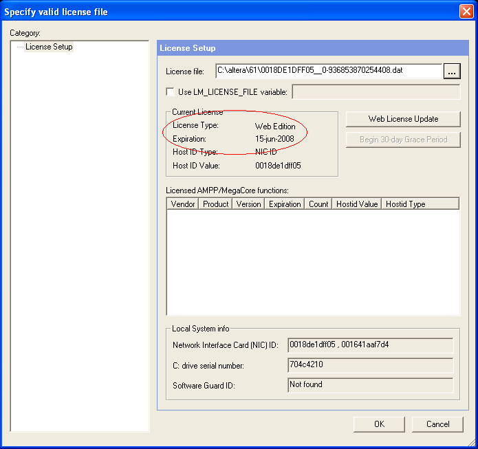
Feb 16, 2000 - In the 'Quartus II Install CD' menu, You are prompted to select one of. Likewise for the Tutorial files. Set up the reference to the license file. Aug 25, 2008 - In the table shown, select “Download” under the label “Quartus® II Web Edition Software. While the software is downloading, you can get your required license file. You are now ready to go through our Quartus tutorial.
Where should I put my future project files? Here are a few guidelines you should adopt when choosing a directory for your project: • Don’t put projects within the Quartus tool directory.
New Quartus versions come out every six months, so placing them within a specific version directory will make them “orphans” once a new version is installed. Even worse, you might lose them if you delete the older tool version. • Avoid paths with spaces in the name since some of the tools don’t like spaces in directory paths. • Use directories where you have read/write access. This sounds intuitive, but sometimes IT departments limit administrator rights. Be sure the folder you create doesn’t require admin rights. Step 1.e: Project Type Select Empty Project, and then click Next.
Step 1.f: Add Files You won’t be adding any files here. Step 1.g: Family, Device, and Board Settings ( Note: You may need to expand window to view more device names) Select the following: Family: Cyclone 10 LP Device name: 10CL025YU256I7G Click Next. Step 1.h: EDA Tool Settings We will be using the default EDA tools and settings so there are no changes to be made. Step 1.i: Summary Click Finish The following screen displays. E gitarrenbau martin koch pdf files free. Step 2: Create an HDL File Hardware Description Language (HDL) We use Verilog as the HDL. If you are familiar with the C programming language but new to programming in an HDL, Verilog is like C in that you place a semicolon ‘;’ at the end of each statement. Step 2.a: Navigate to the File tab (main window), and then select New.
Select Verilog HDL File, and then click OK. Step 2.b: Choose File > Save As. Choose “blink” for the file name. This is your top-level file name and it must match the name of the project name (blink).
Click Save Step 3: Create a Verilog Module Step 3.a: Copy and paste this Verilog code into the blink.v window, and then save the file. // create module module blink ( input wire clk, // 50MHz input clock output wire LED // LED ouput ); // create a binary counter reg [31:0] cnt; // 32-bit counter initial begin cnt Pin Planner. Step 4.b: One at a time, click to highlight the Location column for each pin, then type the pin location for the LED and clk signals as shown below. The rest of the columns will auto populate with data (some with default values that we’ll modify in the next step). Node Name Location LED PIN_L14 clk PIN_E1 You also need to change the I/O standard, Current Strength and Slew Rate columns from their default settings to the values shown below: Node Name Location I/O Standard Current Strength Slew Rate LED PIN_L14 3.3-V LVTTL 8ma 2 clk PIN_E1 2.5V 8ma Step 4.c: To change the I/O standard, double click each cell and a pull-down menu will appear.